

Power Conversion System PCS Factory Production Process Step by Step
2026-11-02
Most people never see what happens before a Power Conversion System is bolted into a solar or storage site. But on the factory floor, it's a different story—raw components are transformed through a step-by-step gauntlet of assembly, wiring, and testing. At UNC, this process isn't just about building units; it's about engineering reliability into every stage. From the first torque check to the final performance validation, each step removes uncertainty. Follow along as we break down the PCS production process and show why what happens inside the factory matters long after installation.
Unboxing and Verifying Every Component Before It Touches the Line
Before a single part moves toward the assembly floor, every box gets opened with a mix of anticipation and scrutiny. Pallets arrive wrapped in layers of plastic and cardboard, and the first step is always a visual once-over: check for crushed corners, moisture stains, or any sign the shipment took a beating in transit. Once the outer packaging clears that initial filter, each component is pulled out and laid on a clean bench, not just tossed into a bin. That slower, deliberate unpacking catches things a rushed inventory scan would miss—a bent connector pin, a scratched housing, a missing gasket tucked under a flap. It’s not about distrusting the supplier; it’s about knowing that one bad part at this stage multiplies into ten problems downstream.
The verification doesn’t stop at looking. Each part gets matched against its spec sheet, but not in a robotic check-the-box way. The person on unpacking duty might run a micrometer over a critical shaft, test a switch’s resistance, or simply thread a bolt by hand to feel for galling. Sometimes the discrepancy is tiny: a tolerance drift of two thousandths, a label that reads “Rev B” when the order called for “Rev C.” Those small catches are what keep a line from stopping mid-shift. It’s tedious work, but there’s a rhythm to it—open, inspect, confirm, set aside. No part touches the line until it has been seen by human eyes and, where it matters, verified by a tool or gauge.
What makes this step genuinely useful is the running log. Any anomaly, even a minor one, gets noted with the lot number and supplier. Over time, that notebook becomes a map of weak points: a particular courier that always damages boxes on the left side, a vendor whose anodizing flakes after three weeks in storage, a batch of fasteners that measures fine but strips under normal torque. That knowledge feeds back into receiving protocols and vendor scorecards. So the unboxing table isn’t just a pit stop—it’s the first quality checkpoint, and it keeps the rest of the line from inheriting someone else’s mistakes.
Assembling the Power Core: IGBT Modules Meet the Cold Plate
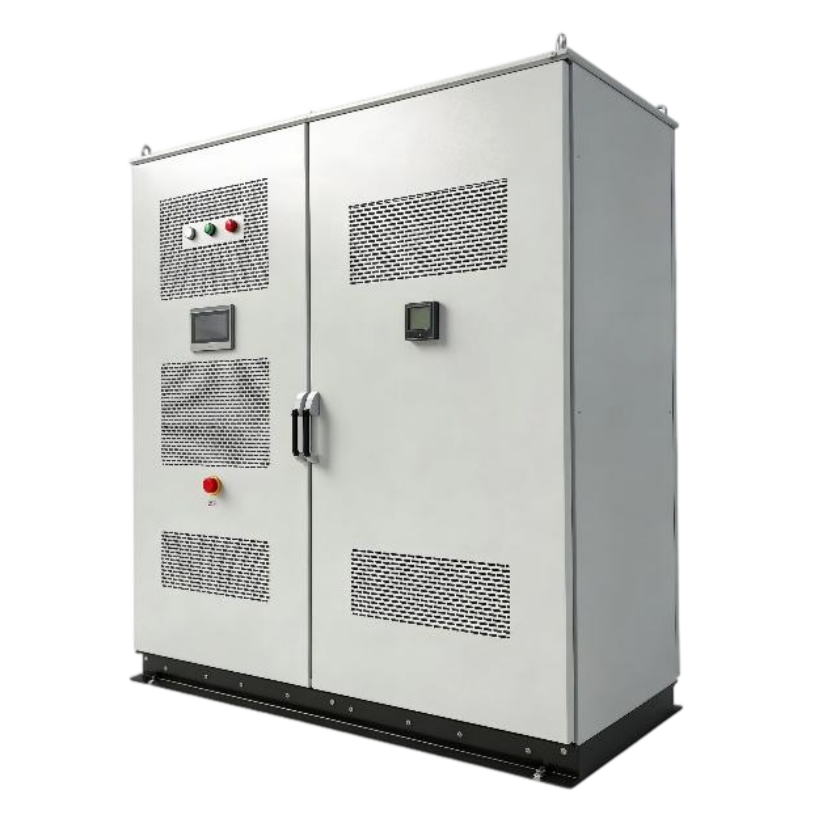
Bringing an IGBT module onto a cold plate is less about bolting parts together and more about managing the hidden war against heat. The module base sits flush against a machined surface, often with a thin layer of thermal interface material filling the microscopic gaps. That interface is where performance lives or dies — too thick and the thermal resistance climbs, too thin and air pockets form under pressure cycling. A good assembly sequence starts with clean, dry surfaces and a controlled torque pattern, so the clamping force spreads evenly across the ceramic substrate inside the module. Skipping this step is how you end up with hot spots that age the solder joints long before the rated lifetime.
The cold plate itself carries a lot of quiet engineering. Internal fin geometry, flow rate, and coolant temperature all shift how the module behaves under load. When pairing an IGBT module with a liquid-cooled plate, the goal is to keep the junction temperature below the derating curve without overchilling the assembly and inviting condensation. Many builders overlook the pressure drop across the plate — if the pump can't push enough coolant through the narrow channels, the plate becomes a bottleneck instead of a heat sink. Matching the module's footprint to the plate's effective cooling zone matters just as much as the thermal paste spec.
What separates a reliable build from a marginal one shows up in the first thermal cycle. Repeated expansion and contraction work the stack like a slow fatigue machine. Modules that are over-torqued or mounted on plates with uneven flatness start to bow, cracking the bond between the baseplate and the ceramic layer. A practical approach is to check the plate flatness with a feeler gauge before assembly, then verify the clamping force with a calibrated torque wrench rather than guessing by hand. It is a small ritual that pays off in lower failure rates and a much longer service life for the drive or inverter.
Routing High-Current Paths with Busbars and Torque-Controlled Bolts
When routing high-current paths, flat copper or aluminum busbars offer a much lower impedance than round cables of equivalent cross-section. The key is to keep the runs as short as the layout allows and to bring the positive and negative conductors close together. This cuts down the loop area, which in turn reduces inductance and improves transient response under heavy load. Busbars also need solid mechanical support, not just because they are heavy, but because short-circuit forces can physically throw an unsupported conductor sideways.
Torque-controlled bolts are the other half of a reliable high-current connection. A busbar joint that is too loose will develop high resistance and hot spots, while one that is over-tightened can deform the bar or crush the plating. Using a calibrated torque wrench with the manufacturer's recommended dry or lubricated torque value gives repeatable clamping force across every bolt. It is also worth rechecking torque after the first thermal cycle, because copper and aluminum expand at different rates.
In practice, routing high-current paths with busbars means planning for both normal operation and fault events. Leave enough clearance for air flow around the bars, but keep them away from ferrous enclosures that can cause eddy-current heating. Mark every bolted joint with a torque witness mark so maintenance crews can spot loosening at a glance. A quick thermal scan after full load is the fastest way to confirm that the routing and torque settings are doing their job.
Bringing the Control Board to Life with Firmware and First Power-Up
The moment of truth arrives when a bare PCB stops being a collection of traces and pads and starts acting like a brain. Loading the first firmware build is rarely a clean, one-shot affair. I usually start by flashing a minimal bootloader over JTAG or SWD, watching the debug console like a hawk for any sign of a clock that refuses to start or a voltage rail that sags under load. The smell of hot solder still lingers in the air as the microcontroller wakes up, and that first acknowledgment byte over UART feels absurdly rewarding—like the board just whispered back that it's ready to work.
First power-up is less about proving the design works and more about discovering which assumptions were wrong. A current-limited bench supply is non-negotiable; I set it to 50 mA and slowly raise the voltage while probing the 3.3 V and 5 V rails for any unexpected dips. One board I brought up recently had a misplaced decoupling cap that turned the reset line into a tiny antenna—every time my hand got near the board, the MCU reset. Fixing that meant scraping a trace and bodging a wire, but it turned a frustrating afternoon into a lesson about layout parasitics. Those early bring-up sessions are where you learn the personality of your own design, quirks and all.
Once the core is alive, the real conversation starts. I write tiny test routines that blink an LED, read back a GPIO state, or spit out ADC values at a slow baud rate—each one a miniature handshake with the hardware. A serial terminal becomes my mirror into the chip's world, and sometimes the board's silence tells me more than a wall of error codes ever could. By the time the first real application firmware runs, the control board has stopped being a schematic and started being a collaborator, one that remembers every solder bridge and every late-night fix.
Running the Full Test Gauntlet: Safety, Efficiency, and Grid Simulation
The phrase “full test gauntlet” gets thrown around a lot, but here it means pushing hardware through abuse that most field installations will never see. Thermal runaway chambers, nail penetration rigs, and overcharge cycles run until cells swell or vent. The goal isn't to pass every test on the first try; it's to map exactly where failure begins, then dial back until there's margin.
Efficiency work is quieter but just as brutal. Round-trip numbers look great on a datasheet, yet real losses show up under partial load, high ambient temperature, and uneven state-of-charge across parallel strings. We measure DC-side and AC-side losses separately, then run 48-hour profiles that mimic a solar farm's clipped output or a data center's step loads. If the number drifts more than half a percent between identical units, that's a teardown trigger.
Grid simulation closes the loop. The test bench recreates weak grids, voltage sags, frequency excursions, and harmonic distortion from nearby inverters. We also inject faults on the AC side to confirm anti-islanding and ride-through behavior match the utility interconnection agreement. Passing means the system doesn't just survive the simulated grid—it behaves like a good neighbor on it.
Packing Each Unit to Survive the Journey from Factory Floor to Site
Every unit leaves our floor with the assumption that the road will be rough, the weather uncooperative, and the handling less than gentle. We start by anchoring internal components to a steel base frame, then wrap shock-sensitive sections in closed-cell foam rather than relying on loose fill. Corners and edges get reinforced caps, because those are the first points to catch a forklift blade or a doorway.
Moisture is often the quiet destroyer in transit, so each crate carries a desiccant pack sized for the longest realistic route, not the shortest. We also seal joints with a non-hardening butyl tape that keeps out dust and humidity without making disassembly a fight on site. Where a unit has any moving part, that part is locked in its neutral position with reusable braces, so it arrives ready to align, not to repair.
Finally, we load units in the reverse order of installation, with the first-needed item at the back and the last at the front. This cuts down double-handling and keeps the site team from digging through a full container just to reach a single connection kit. The goal is simple: the packaging should be predictable, so the unpacking is just as straightforward.
FAQ
The line usually starts with incoming component verification, then moves through subassembly of power modules and control boards, followed by main chassis assembly, internal wiring, firmware flashing, initial power-up tests, full-load burn-in, final safety checks, and packaging. Each station has a traveler document that records torque values, test results, and operator sign-offs.
IGBT or SiC modules are treated as electrostatic-sensitive devices. Operators wear grounded wrist straps and work on ESD-safe benches. Dielectric strength and thermal interface material thickness are checked before the modules are bolted to the heatsink or cold plate, and torque wrenches with preset limits are used to avoid uneven pressure.
After the internal cabling is completed, a continuity and hipot test is run on the harness. Automated test fixtures check pin-to-pin continuity, insulation resistance, and sometimes low-voltage signal injection. Any mismatch between the wiring diagram and the measured netlist stops the unit from moving to the next station.
Liquid-cooled PCS units go through a pressure decay test with dry air or nitrogen at a specified pressure, typically holding for several minutes. Air-cooled units get a fan speed and airflow check. Thermal sensors are also read back through the control board to confirm they report plausible room-temperature values.
Each unit receives its application firmware through a secure programming fixture, followed by a configuration file that sets grid code parameters, communication addresses, and protection thresholds. The configuration is checksummed and logged against the serial number, so any unauthorized change later is traceable.
The unit is connected to a regenerative or resistive load bank and operated at rated power for a set duration, often 2 to 8 hours depending on the product class. Technicians monitor efficiency, harmonic distortion, temperature rise, and fault logs. Units that trip or drift outside tolerance are routed to a rework bench before retesting.
The finished PCS goes through a final hipot test, protective earth continuity measurement, and leakage current check. Labels and warning markings are inspected against the order's regional requirements. A final visual inspection looks for loose hardware, cable pinch points, and debris inside the enclosure.
Units are often wrapped in VCI film or sealed in a moisture-barrier bag with desiccant, then placed in a foam-cushioned wooden crate or reinforced carton. Tilt and shock indicators may be attached to the outside, and the packaging is designed so the unit can be lifted with a pallet jack or forklift without opening the crate.
Conclusion
Every PCS build starts with a deliberate unboxing ritual: each IGBT module, cold plate, busbar, and control board is inspected against the bill of materials before any part reaches the assembly station. Once cleared, the power core takes shape—IGBT modules are mounted onto the cold plate with a thin, even layer of thermal interface material, and torque wrenches click at specified values to avoid micro-deformation. High-current paths follow next, with laminated busbars routed to minimize stray inductance; every bolt is torqued in a cross pattern, and the joints are later checked with a calibrated wrench to confirm consistent clamping force across the stack.
With the mechanical heart in place, the control board is flashed with the latest firmware and the unit gets its first low-voltage wake-up—engineers watch the boot sequence, check gate driver signals, and verify communication before any main power is applied. Then the PCS enters the test gauntlet: hipot and insulation resistance tests come first, followed by efficiency mapping at multiple load points, protective function trips, and finally grid simulation where the unit must ride through voltage dips, frequency swings, and reactive power commands. Only after passing all stations does the PCS get packed—custom foam cradles, desiccant packs, and a double-wall crate are used, with shock and tilt indicators attached so anyone at the receiving dock can tell if the unit was mishandled in transit.
Contact Us
Contact Person: Manager Leng
Email: [email protected]
Tel/WhatsApp: 8613764878967
Website: https://www.unc-energy.com