

PVC Pipe Production Line Supplier Shares Proven Tactics for Higher Output
2026-11-02
Boosting output on a PVC pipe production line isn’t just about running machines faster—it’s about smart, proven adjustments that compound over time. In this post, COMRISE shares field-tested tactics that go beyond generic advice, revealing exactly how to squeeze more production from your existing setup without sacrificing quality. If you’re tired of hearing the same old “increase speed” tips and want actionable, supplier-level insight, you’re in the right place.
Stop Overlooking Barrel Zone Balance When Pushing Line Speed
Raising line speed often feels like a simple lever: turn it up and watch output climb. But the thermal profile inside the barrel rarely follows in lockstep. Each zone has a different job, and as throughput increases, the residence time drops. That means polymer spends less time absorbing heat from the barrel wall. If you keep the same setpoints, the melt temperature can drift lower even though the zones read steady. Operators tend to compensate by cranking the screw speed or pressure, which adds shear heat unevenly. The real fix is rebalancing the zones for the new throughput, not chasing a single temperature reading.
Imbalance shows up first in subtle ways: a slight rise in melt pressure, a dull surface finish, or an occasional unmelts speck. Left unchecked, the front zones overwork while the rear zones underdeliver. That gap forces the screw to do extra mechanical work, which can degrade heat-sensitive resins or create inconsistent part density. A better approach is to map the barrel profile at the target speed before committing to it. Bump the line speed in small steps, wait for steady state, and log the actual melt temperature at the die. Use that data to shift heat toward the zones that need it most, rather than pushing all zones up equally.
Balanced barrel zones are not a set-and-forget state. They need to be re-tuned whenever throughput changes by more than a few percent. Watch the relationship between zone setpoints and actual melt temperature: if the gap widens, you are asking the heater bands to fight the screw instead of working with it. Small moves, a few degrees at a time, will keep the process stable and the product consistent at higher line speeds.
The Screw Wear Pattern That Quietly Caps Your Output
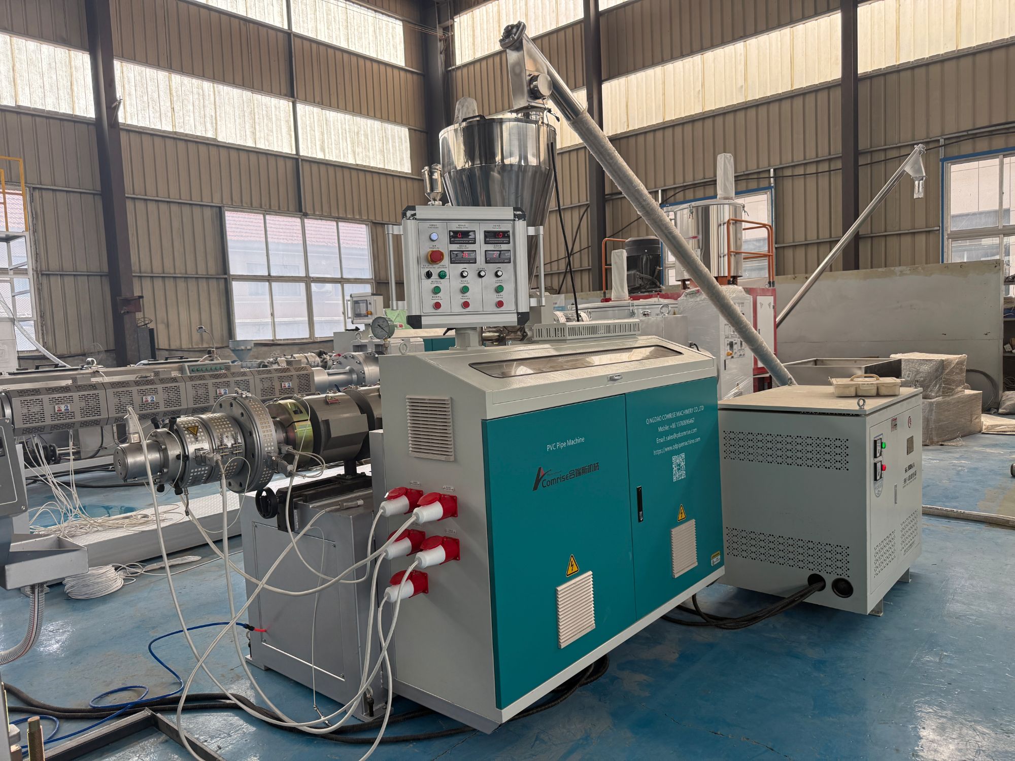
Most operators catch the obvious failures—cracked flights, heavy barrel scoring, a seized check ring. The real output thief is quieter. It shows up as a polished band on the flight tips near the end of the metering section, usually 2 to 4 diameters before the discharge end. That band isn't random abrasion; it's a wear signature created by the screw bending slightly under pressure and dragging the flight tips against the barrel wall in a repeating axial pattern. Because it happens slowly, the line just runs a few percent slower each month and nobody ties it back to the screw.
Once the flight-to-barrel clearance in that zone opens up from a snug 0.1 mm to 0.3 mm or more, the melt no longer moves only forward. A fraction starts slipping backward over the flight tip, driven by the steep pressure gradient. This leakage doesn't trigger alarms—temperatures stay stable, melt pressure looks normal, and the product may still pass QC. What changes is the energy per kilogram and the real throughput ceiling. You can push the same screw speed, but the output plateaus lower than it did when the screw was new.
The giveaway is often hidden in the trend data. Watch for a steady but small decline in output at constant rpm over several hundred hours, combined with a slight drop in specific energy. If you pull the screw, don't just look for gouges. Run a straightedge along the flight tips in the metering section and look for light gaps, or measure the flight height every 50 mm. A polished, slightly rounded land in that one zone is the pattern that quietly caps your output—and it rarely fixes itself.
Vacuum Calibration Tweaks Most Operators Skip
Most techs trust the factory calibration sticker and call it done, but a cold cathode gauge drifts differently after it has seen process vapors. One tweak that gets skipped is a two-point span check using a known leak valve and a blanked-off chamber — it takes ten minutes and catches offsets that a single-point zero can hide.
Another overlooked step is letting the sensor stabilize at actual working temperature before tweaking the zero pot. If you null a Pirani gauge while the bridge is still warming up, the curve shifts once it reaches thermal equilibrium. Also, for diaphragm gauges, loosen the case screws and re-torque them evenly before calibration; case stress can skew the reading by a few mTorr.
If you are using a capacitance manometer, the zero offset often changes after cycling from atmosphere to vacuum several times. A quick fix is to record the reading at a hard vacuum after a 15-minute pump-down, then subtract that offset in the controller rather than chasing the pot each time. This keeps the calibration history clean and makes drift easier to spot later.
Cut-Off Precision: A Faster Line Demands Better Blades
Speed pushes every component harder, but the cut-off blade is where the real cost of poor quality shows up first. At higher feed rates, a blade with ordinary edge retention starts to deflect, overheat, or leave micro-fractures along the cut face. That forces rework, shortens tool life, and turns a fast line into a bottleneck at the next inspection station.
The difference usually comes down to carbide grade and edge preparation. A blade that holds its corner geometry under thermal load will slice through bar stock or tubing without walking off the cut line. On high-volume lines, pairing the right blade with controlled coolant flow and a rigid arbor keeps the cut square, the burr small, and the scrap rate low—without slowing the cycle.
If throughput keeps climbing, blade changes should be planned around measurable wear, not guesswork. Tracking cut counts and kerf drift makes it easier to swap in a fresh edge before finish quality drops. That kind of attention to blade condition is what separates a line that merely runs fast from one that runs fast and still holds tolerance.
Pre-Heating Compound? The Overlooked Warm-Up Step
Most people skip the warm-up because it feels like wasted time—there's a compound ready to go, so why wait? But a cold compound behaves differently. It might be too thick to spread evenly, or its reactive parts haven't loosened up enough to bond properly. That thirty-second pause before the real work starts can mean the difference between a surface that holds and one that peels away in a week.
Think of it like stretching before a run. The compound's molecular chains need a few moments at operating temperature to relax and align. If you rush in, you'll notice uneven texture, lumps, or a weaker final set. Even seasoned users get impatient, but those who've dealt with failed applications know the pre-heat isn't optional—it's the quiet step that makes everything else stick.
Next time you're about to apply or mix, give the compound a chance to wake up. A low, steady warm-up costs almost nothing, yet it transforms a mediocre result into a reliable one. Once you've felt the difference, skipping it feels like building on sand.
Melt Pressure Spikes as Early Warnings, Not Just Alarms
In extrusion and molding processes, a sudden spike in melt pressure often triggers an immediate shutdown or alarm. But experienced operators know these spikes carry more than just a signal to stop—they are early warnings of developing issues like material degradation, screw wear, or feed inconsistencies. By reading the shape, duration, and frequency of pressure spikes, engineers can pinpoint whether the problem is upstream in the feeding zone or downstream near the die, long before a complete failure occurs.
Treating melt pressure spikes as diagnostic data rather than nuisance alarms changes how teams respond. For instance, a brief, sharp spike at regular intervals might indicate a broken solid bed or a poorly mixed additive, while a gradual rise followed by a plateau could point to screen pack fouling. Instead of simply resetting the system, operators can log these patterns, correlate them with raw material batches or barrel temperature profiles, and adjust parameters proactively. This approach reduces unplanned downtime and extends the life of screws, barrels, and melt filters.
To use spikes effectively, facilities need to move beyond threshold-based alarms. High-frequency pressure transducers and data logging allow operators to review pressure signatures after each run. A spike that once forced an emergency stop can become a teachable moment—revealing, for example, that a specific colorant raises viscosity enough to warrant a lower screw speed. Over time, these insights build a preventive maintenance schedule driven by the machine’s own pressure language, not just fixed time intervals.
FAQ
Inconsistent melt temperature across the die. Many operators chase screw speed, but if the melt isn't uniform, you get wall-thickness variation and surging, which forces you to run slower than the line could handle.
By auditing the existing line's drag points — things like worn barrel heaters, misaligned calibrators, or undersized vacuum pumps. Fixing these often unlocks 10–15% more output with zero capital expenditure.
Because the new screw's compression ratio or flight depth doesn't match the original tooling. Even a small mismatch changes residence time and shear, so the material either degrades or doesn't plasticize fully, and the line gets dialed back.
A lot. If the dry blend varies in bulk density, the extruder feed throat starves or floods unpredictably. Consistent bulk density from the mixer keeps the screw full and lets you hold a higher stable rate without surging.
Not always. Beyond a certain point, faster haul-off can stretch the pipe while it's still too hot, creating residual stress and out-of-spec ovality. Sometimes raising output per RPM through better temperature control beats simply running faster.
Daily checks of screw cooling and vacuum calibration. If the screw core temperature drifts or the vacuum slots clog, you lose control of the melt seal and pipe dimensions, and then you're forced to slow down.
A switch to a lower K-value resin or a different stabilizer package can lower melt viscosity and allow faster throughput, but it also changes heat history. Without adjusting barrel zones, you risk yellowing or die buildup, so the rate gain disappears.
Melt pressure before the screen pack and die, plus haul-off motor current. Together they reveal if the screw is filling properly and whether the pipe is being pulled under excessive tension, which are early signs of a looming slowdown.
Conclusion
Many PVC pipe producers chase line speed by simply raising screw RPM, but the suppliers who consistently hit higher output focus on less obvious adjustments. Balancing barrel zone temperatures instead of running every zone hot stops surging and stabilizes melt flow. Watching for specific screw wear patterns—like reduced root diameter or polished flights—alerts you to output losses long before a full failure. In vacuum calibration, small shifts in tank position and water flow that most operators skip can eliminate drag and allow a faster puller speed. And when lines accelerate, cut-off precision becomes critical: dull or mismatched blades create burrs and jams that force slowdowns, so blade changes should follow a schedule tied to line speed, not just visible wear.
Pre-heating compound before it enters the extruder is another overlooked warm-up step that cuts motor load and improves melt uniformity, especially with high-filler recipes. Instead of treating melt pressure spikes as simple alarms, smart teams read them as early warnings—catching screen pack blockage, feed bridging, or temperature drift before they cause rejects or downtime. A supplier who shares these proven tactics knows that higher output is not about one big change, but about stacking small, repeatable gains. By tightening each of these zones—barrel balance, screw condition, calibration, cutting, pre-heat, and pressure monitoring—a line can run faster without sacrificing wall thickness or ovality. The result is more meters per hour from the same machine, lower scrap rates, and fewer unplanned stops.
Contact Us
Contact Person: LISA LEE
Email: [email protected]
Tel/WhatsApp: +86 13780696467
Website: https://www.qdpipemachine.com